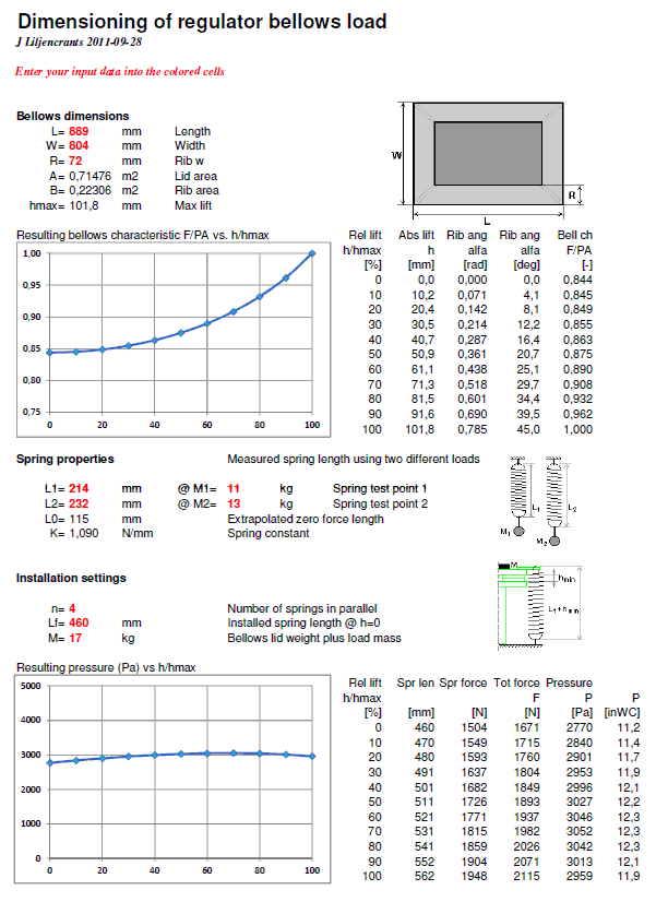
An Excel sheet is provided, from which pressure vs. lid lift is computed. This follows from the easily measured dimensions of the bellows and the springs, and to which length the springs are adjusted, with attention to any additional weight loading of the bellows lid.
Theory
With a reservoir or regulator bellows the externally applied lid force is that from a spring and/or weight, including the weight of the upper lid itself. A weight will give a constant force while a spring generally delivers a greater force the more the bellows is expanded. This force is balanced by the pressure inside the bellows. An obvious and nominal part of this force is lid area times pressure. But there is also another force acting on the lid, namely from the bellows ribs. This force component will vary depending on filling degree, or lift.
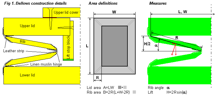
Fig. 1 is a section at the edge of a typical inward
folding bellows. In smaller bellows the ribs may be made
from cardboard or plywood, covered by motor cloth. In the
bigger example shown the ribs are from wood, chamfered
along their edges, joined by glued-on muslin hinges and
air tightened by flexible leather strips. The relevant
measures to characterise the bellows are shown at right,
lid length L and width W, and rib width R. All these
measures are taken at the hinge flexing lines.
The oblique red arrow represents the force from internal pressure acting on the upper rib. The magnitude of it is pressure times rib area. This can further be split up into vertical and horizontal components. These will vary in size, depending on filling state, indirectly defined by the rib angle α.
With an inward folded bellows, as illustrated above, then
the vertical component on the ribs pulls the lids
together, it counteracts the outward pressure on the lid
which balances the weight or spring. This effect is most
pronounced when the bellows are little filled since the
vertical component decreases with growing a as the lid lifts. The horizontal
component works the opposite way, it grows with α,
and it makes the ribs to wedge the frames apart, it
cooperates with the pressure on the lid. The total result
is that when you fill a single, weight loaded inward
folded reservoir the pressure decreases as you
fill it. Or seen the other way, to maintain a constant
pressure the externally applied lid force must increase as
the bellows expands. This is the reason an inward folded
bellows is preferably loaded with springs. By selecting a
suitable spring constant you can then tune the system to
render essentially constant pressure, independent of how
much the bellows is expanded. It must then be recognized
that a spring is characterized not only by its force, but
also by its spring constant, i.e. how much its force
increases per unit of elongation. With a given spring the
force is easily set by adjusting its support point. But
its spring constant cannot be modified, this depends on
its mechanical design parameters, like material, diameter,
number of turns, and wire gauge. The spring constant is
seldom advertized in catalog data, but can easily be
measured by a procedure outlined below, with fig 8.
In an outward folded bellows the rib forces work the
other way. So when you fill a single, weight loaded outward
folded reservoir the pressure increases as you
fill it. And even more so if the bellows is spring loaded.
Accounting for the forces from the folding ribs, the relation between the external bellows compression force F and pressure P can be formulated as a bellows equation, in the following form representing an effective lid area:
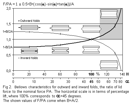
F/P = A ± B*0.5*(cos(α)-sin(α)*tan(α)) [m2]where A is the lid area, B is folding rib area (one layer only, as seen in a top projection drawing of the bellows collapsed, see fig 1), and α is the opening angle of the folds. Plus sign for outward folds, minus for inward.
 The 0.5*B factor represents the
rib area, reduced by lever action. The cos factor is for the
vertical component of the rib force, the sin factor for its
horizontal component, and the tan factor is for how that
horizontal component is wedged into a vertical force
component toward the lid.
The 0.5*B factor represents the
rib area, reduced by lever action. The cos factor is for the
vertical component of the rib force, the sin factor for its
horizontal component, and the tan factor is for how that
horizontal component is wedged into a vertical force
component toward the lid.A reference point is α=45 degrees, ribs at right angles to each other. Then the complicated coefficient for B becomes zero and pressure equals the nominal P=F/A. This point is taken to define a nominal 100% lift of the bellows lid. Depending on rib thickness or other structures a bellows can never collapse all the way down to 0% and zero angle.
A reservoir or regulator bellows is normally supplied from some power machinery and the forces involved may be quite large. With an inward folded bellows there is a hazard inherent from the rise in the F/P characteristic shown above. Keeping constant pressure, as angle grows you need a progressively greater force to balance it, indeed infinite force at α=90 deg. It is essential that you limit this angle to protect the bellows from such overload, otherwise it will be blown out and ripped apart. Usually you do that with a safety pallet on the lid, operated with a string or a finger toward some fixed structure. Normally you would allow a lid to rib angle α no more than about 45 degrees; you should avoid entering the shaded area in the graph above.
In the form shown the formula tells how the force on the lid varies with lift, given constant pressure. One may alternatively have use for its inverted value, telling how pressure will vary, given constant force. See e.g. fig. 6 below.
Practical measurements
Bellows pressure vs. lift characteristic
This section reports a sequence of measurements on a Wurlitzer 35x32 inch regulator bellows. These validate the bellows characteristic formula above and illustrate the influence from how the bellows is loaded.They also bring out the effect from stiffness in hinges, leather strips, and corner gussets. Tilting the bellows into a vertical position and letting the top lid move freely it was found that it would settle at about 70 mm lift. This is a neutral point where the stiffness of the hinges and leather do not contribute to the bellows force.
Here a set of dimensions for this bellows:
| Quantity |
Symbol |
Metric |
Trad |
Note |
| Lid length |
L | 889 mm | 35,0 " | Between hinges |
| Lid width |
W | 804 mm | 31,7 " | Between hinges |
| Rib Width |
R | 72 mm | 2,83 " | Between hinges |
| Minimum lift |
46% | 47 mm | 1,85 " | Set by stop
blocks |
| Nominal full lift | 100% | 102 mm | 4,0 " | =R*sqrt(2) |
| Maximum lift |
120% | 122 mm | 4,8 " | Set by spacers when gussets were glued |
| Lid area |
A |
0,715 m2 |
7,70 sqft |
=LW |
| Rib area |
B |
0,224 m2 | 2,41 sqft |
=2R(L+W-2R) |
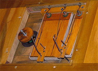 Fig
3. View of the under side of the 'air control board' on
the lower bellows lid, where air is blown in from the
supply trunk.
Fig
3. View of the under side of the 'air control board' on
the lower bellows lid, where air is blown in from the
supply trunk. The air control board carries a cone valve, a narrow pallet, and a wide one. In normal regulator operation these are controlled by sticks toward the upper lid. As the top lid sinks, they open in sequence in order to increase supply. Supply is then cut off at about 100% lift where the cone closes against its seat. The top lid can rise slightly more than this because the cone is attached to its shaft with a small spring. If the bellows for some reason would tend to be over filled, then this spring is compressed and an evacuating safety pallet on the upper lid is pulled open by a tape toward the lower lid.
A temporary test rig was set up to measure bellows pressure vs. lid lift at a few different load conditions. During this test the regulator cone valve was removed and a pressure transducer was connected to its shaft mounting hole. The bellows outlet ports were blocked and the bellows was blown from a shop vac, connected to a box covering the control board. A stationary bridge, constructed from wood sticks and clamps, carries a scale to measure lift, right in fig 4, beside the pressure indicator.
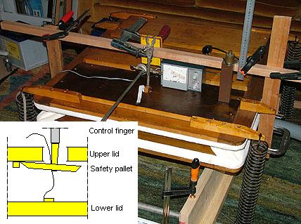
The safety pallet was used as a special regulating device during the test. The bridge also holds a finger that can be manually adjusted to a certain height. When blowing the lid to rise and it reaches that place, then the pallet is pried open by the finger and lid movement stops. Pressure inside is then independent of how much air you blow into the bellows, once enough to keep the pallet open. But of course the blower must not be too strong for the pallet to release the surplus air.
During the test the pallet actuating tape was adjusted longer than normal, such that lift could be driven all the way where the gussets were tensioned, a somewhat risky operation.
 Fig 5. The lid loaded with 102
kgs of various tools, accumulators, etc.
Fig 5. The lid loaded with 102
kgs of various tools, accumulators, etc.The weights are placed with their center of gravity to coincide with the bellows center, such that the top lid moves in parallel to the bottom lid.
Measurements in the red traces of figs 6 and 7.
Lift is limited downward by internal stop blocks and upward by how the corner gussets were glued at fabrication. For reference, marks in the middle of fig 6 show the opening points of the various valves in the regulator, arrows pointing into the ranges of lift they are open.
Each measurement series is accompanied by an ideal graph in black, namely the pressure as computed from the bellows characteristic formula above. Then a constant force was presumed, such as you get when the lid is loaded by weights.
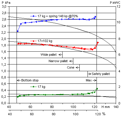 Fig 6. Measurements of
pressure vs. lift.
Fig 6. Measurements of
pressure vs. lift.The bottom graph in green was taken on the bare bellows, with no external load. The lid weight was found by computational trial until the theoretical graph matched the measured data at about 70 % lift where the hinge stiffness force was known to be zero. That way lid weight was estimated to be 17 kg.
The pressure difference at other lifts between the measurement and the theoretical prediction is due to hinge stiffness. Recomputation of that into force is shown separately in fig 7.
The heavy weight load data in red verify two aspects of the theory: how much pressure increases due to that load change, and how pressure drops with increasing lift. Again the additional forces from hinges were computed and show a nice agreement with the earlier result.
The blue data points for the spring loaded case show an essentially constant pressure. This means that the spring constant is about right. In the main range of lift the spring force varies roughly the same way as the bellows characteristic F/PA.
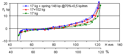 Fig
7. Lid force developed by hinge leather and gussets, as
found from the three data series, given in kp = kilogram
force.
Fig
7. Lid force developed by hinge leather and gussets, as
found from the three data series, given in kp = kilogram
force. From the bellows characteristic and the measured pressure the bellows loading force was computed. In the weight loaded cases (green, red) the known loading weights were then subtracted to leave the hinge force as a residual..
The spring loaded case (blue) also requires accounting for the spring stiffness that causes the force to increase with lift. The data shown is when you assume the total stiffness for the four springs to be 0.50 kp/mm. This value was obtained using the direct spring measurement procedure outlined below.
Spring constant, stiffness or compliance
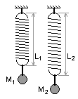 Hang
the spring from a fixed support and load it with a weight
such that the coil is somewhat extended. Extension is
necessary as most coil springs are pre-tensioned, they must
have a certain load before they expand any at all. Make two
passes using different weights M1 and M2, and
record the corresponding extended lengths L1 and L2 of the
spring. The length is most conveniently measured between the
spring end supports.
Hang
the spring from a fixed support and load it with a weight
such that the coil is somewhat extended. Extension is
necessary as most coil springs are pre-tensioned, they must
have a certain load before they expand any at all. Make two
passes using different weights M1 and M2, and
record the corresponding extended lengths L1 and L2 of the
spring. The length is most conveniently measured between the
spring end supports.Fig 8. Rig to measure the spring constant.
In practice most people would specify the result in terms of loading weight, e.g. as M/X in kg/m or lbs/inch. The physically correct unit for the spring constant, or stiffness, is however force/elongation, e.g. in SI units Newton/meter, N/m. A mass M will develop the gravitational force F=Mg, g=9,81 m/s2. So stiffness is properly defined as
An alternative measure of the same thing is its inverted value, the spring compliance C=1/K, measured in m/N, but in practice maybe shown in cm/kg, or inches/lb.
The following rules may be useful to estimate how to make a new spring, projecting from an existing one:
- Given wire and coil diameters, compliance is proportional to number of turns n.
- Given wire diameter and number of turns, compliance is proportional to coil diameter D to the third power.
- Given coil diameter and number of turns, stiffness is proportional to wire diameter d to the fourth power.
Determining a suitable bellows spring and weight load
Its suggested use is that you first enter your bellows dimensions and spring data as per fig 8. Then the speadsheet calculates the resulting pressure vs. lift characteristic. The practically interesting feature is that you can study how this characteristic comes out, depending on how many springs you use, how much they are stretched, and whether you add weights to the lid.