 1. The
whistle parts1. The
whistle parts
1. The
whistle parts1. The
whistle parts
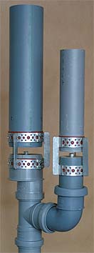
4. Demonstration modelThis photo shows two rather unromantic whistles fabricated like in the drawing above, from 75 and 50 mm (3 and 2 inch) PVC drainage tubing. The internal disks are turned from 1/2 inch plywood to press fit tolerance. Their notes using the 3:1 scaling rule form the fifth interval G and D. Since the bell tubes are made with about 30% excess length they can be tuned down as far as to a fourth lower by pushing up their top disks to increase L.These two whistles were simultaneously blown from an industrial fan that delivers about 4 kPa pressure (17 inWC, 0.6 PSI) which results in about 115 dBC sound pressure level at 1 meter distance. Slit widths are 1.0 and 0.8 mm respectively. The whistles are connected to the fan with a T joint, such that the fan is free blowing through the third opening of the joint. The whistles sound when this opening is covered with the hand. In the sample the higher whistle is tuned down to #C to form a diminished fifth interval. |
 |
 |
The sound
clip was recorded at 6 m
distance from the whistles, outdoors
facing a park. Background is some reverberation from surrounding houses
and a weak titter from sparrows. In this spectrum of the sound the harmonic numbers for the 3 inch whistle 370 Hz G are identified with red figures. Harmonics for the 2 inch 550 Hz #C with green. |
| Blowing with steam the initial
pitch
rise makes for an appealing howl characteristic that is less pronounced
using air. This sketch shows a workaround to increase the glide with
air. Below the top of the bell a gasketed (red) piston is
added, with a spring pulling it upward. The space between top and
piston is connected with a tube to the foot of the whistle. When
blowing pressure (blue) is turned on, the piston moves down such that
the
effective bell length is reduced and pitch rises. Unless you have close
control of spring force, piston area, and pressure it is wise to
limit the piston travel with a thread or chain inside the spring
(green). This sound clip illustrates the action with the 3" whistle alone. It was tuned down to about E which reduced sound level to 107 dBC at 1 m distance. |
 |