This note reproduces my posting to the
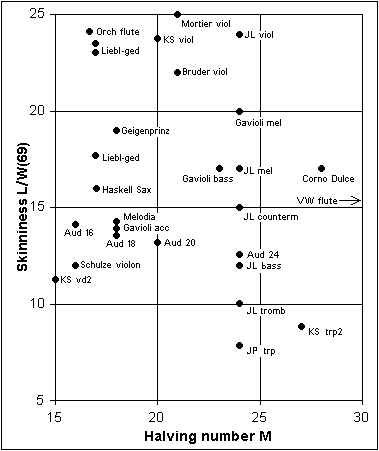
MMD-Pipes Forum on 2002-01-25. For quite some time I have contemplated to unify the scattered collection of scaling data I have at hand. The recent posting by Marc Elbasani of a few tables proved a trigger - here a consequent avalanche. First some propaganda: Apart from various definitions and comments which you can find in my article http://www.mmdigest.com/Tech/pipesRecipe.html , from there you can also download a simple Excel spreadsheet, called violpip.xls. (Now, afterwards, I regret that name, it is not at all limited to some specific kind of pipes). That spreadsheet contains the basic formulas to compute pipe dimensions from design parameters. The sheet has two headers, one for inches, the other for metric units, you can follow instructions there to select which one to use. The essential thing is that you yourself are supposed to provide the crucial design parameters, marked in boldface. The two most important of these are |
||
L/W(69) | 'Skinniness' | The ratio between nominal length L (half wave) and pipe width W, for note MIDI 69, that is a'=440 Hz |
M | 'Halving number' | How many semitones up the tonal scale you go until a width measure is halved |
These two parameters are the
only
ones you need to get a general overview. On top of those you can
optionally
specify foot height F and
wall thickness T to get some
measures of pieces to build the
pipe from. These other measures generally have no acoustical
consequences. Now, and many times before, I have used that spreadsheet for a reverse operation: given a few example pipes, a table, or a drawing of a rank, then find out what are those parameters. Essentially cut and try L/W and M until the resulting table matches the data you have. (To find out what is a best match you generally would have to invent some auxiliary formulas to the side). This operation was particularly simple with the tables Marc just supplied because M was already given, no need to guess. And his tables were obviously generated by a program similar to my spreadsheet, matches come to within fractions of a percent, errors explicable by truncation of number of decimals. |
|
|
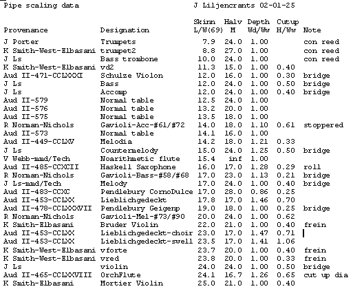
Aud II stands for Audsley:
Art of
organ building, vol 2. Page and figure numbers. J Ls is for various ranks in my own organ. Other entries are names in a tradition chain, to the extent I am aware. Here generally the last name indicates who posted the background data to this Forum. All parameters in the table are dimensionless, they give ratios between measures. This means they are the same, no matter you use inches or millimeters. Wd/Ww is the ratio of internal widths: depth/width. 1.0 means square pipe. For the non-square pipes I used W=sqrt(Wd*Ww) in the expression for skinniness (width of a square, having the same area as the rectangle). H/Ww is the cut up as fraction of the (mouth=internal) width. |
|
There is
no data on the air band
thickness. This has to be determined separately; a main additional
factor is then
the blowing pressure. About this, refer to http://www.mmdigest.com/Tech/isint.html There is a large number of factors, additional to L/W and M, that determine what the pipe will finally sound like, those controlled in the voicing. To mention a few: - Pressure and airband thickness influence power level. Pipe pressures can be individually set by toe holes or foot throttles. - Languid or cap adjustment control airband direction, speech onset, and spectral composition. - Flue nicking introduces controlled turbulence and tends to reduce chiff. - Cut up must match frequency, pressure and air band thickness. - Braking devices like ears, rolls, bridges, freins, or double languids enhance higher harmonics and enable lower cut up. |