Resonators and Q value

by Johan Liljencrants

Resonances, resonators, and characteristics of those is an engineering topic of widespread use, particularly in electronics, acoustics, and mechanics. A complete treatment of this involves a good deal of math that many students have to endure. However, let us here just briefly illustrate with a few examples what this is all about, and point out a few practical standard thumb rules in the area.

What is a resonator

A resonator, whether electrical, mechanical, acoustical, or whatever, always involves an inertial element M and a compliant element C. You can excite the resonator by injecting a certain energy into it. In the resonator this energy will then periodically oscillate between static (in the compliant member C) and kinetic (in the inertial M). Because of inevitable losses this oscillation will decrease with time if the resonator is left alone. In circuit theory the loss mechanism is represented with a resistance R.

It is customary to characterize a resonator with three secondary properties which can be computed from its primary R-M-C elements:

  • The resonance frequency F0, how many cycles per second in the oscillation.
  • The Q value, the 'Quality factor', e.g. indirectly telling how long oscillation will go on after a momentary excitation, or the 'sharpness' of the resonance.
  • The impedance level, which gives a relation between the oscillating energy and the observed excursion, e.g. in terms of voltage, displacement, pressure, etc. (This point will not be further covered here).
There are two special ways to look at a resonator that are particularly illustrative. One is the impulse response in the 'time domain', the other is the frequency response. They are classical methods that can be worked with 'by hand' using simple instruments. Modern computerized analyses may use several other methods, e.g. with chirp, noise, or pseudo-random (MLSSA) signals, and sophisticated signal processing. Often results of such analyses are presented in the end, recomputed as one or both of these simple representations.

These two responses are interrelated, they tell the same story about the resonator, but in different ways. You can translate from one to the other analytically by way of the Laplace transform, something that is way too complicated to enter here. You can also transform between signals in the two domains in a computer, using the Fourier transform (FFT).

A general observation in connection with the transform theory is that time is an inverse to frequency, they have a dual relation. In technical jargon you can say that the 'time window' times the 'frequency window' is unity. An important consequence is, in plain words:

  • Something that changes rapidly in time occupies a wide range in frequency.
  • Something that occupies only a narrow range of frequencies cannot change rapidly in time.

Time domain impulse response

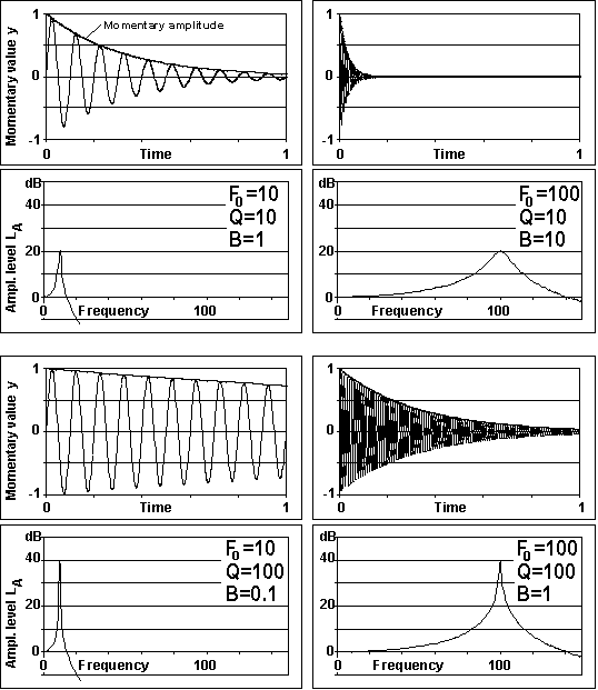
You set the resonance in motion with a single impulse, and then you study how the resonance motion develops with time. For example, pluck a string, strike a xylophone, and record the sound wave. Typical resulting waveforms are shown in the upper graphs in each pair in fig 1, momentary deflection (or voltage, current, pressure, speed, etc.) vs. time.

The vertically displayed momentary value obeys the basic function of time t:

y = A0*exp(-π*F0*t/Q)*sin(2*π*F0*t+φ)

where F0 is the resonance (or natural) frequency, and Q is the quality factor. We return to these below. φ is a phase angle that depends on the precise start conditions and is mostly of little interest. The formula has a sine factor that portrays the oscillation. The initial amplitude A0 together with the exponential function define a decreasing momentary amplitude.

Frequency domain continuous response

You excite the resonator continuously with an external sinusoidal signal, and then you study how the resonance motion behaves when you vary the frequency of that signal. This exemplifies what is often thought of as filtering. Typical corresponding outcomes are shown in the lower graph of each pair in fig 1, the amplitude (=peak value of momentary deflection) vs. frequency. The frequency response displays its resonance peak where the exciting frequency coincides with the resonance frequency.


qval1.gif  
Fig 1. Four pairs, in each: top, impulse response, bottom, frequency response. Left column low resonance frequency, right colmn high frequency. Top row low Q, bottom row, high Q. The upper left and lower right pairs have the same resonance bandwidth B=1, and hence the same decay rate in their time responses.

Formulas for frequency responses are generally straight forward, but rather tedious and unweildy to derive directly from a circuit diagram. Here is an example that applies to the lowpass case of Fig 1 and Fig 5, top. The magnitude of the ratio between output and input, as function of frequency F, can be found as

H = F02 / sqrt{ (F0F/Q)2 + (F02-F2)2 }

When frequency F=0 this reduces to H=1, and at resonance, for F=F0, we get H=Q.


Logarithmic scales and dB

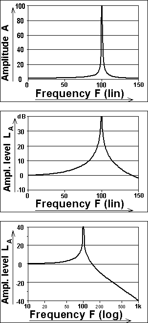
The frequency responses of Fig 1 include also another feature, ubiquitously used: the amplitude is displayed on a logarithmic scale, in decibels (dB). Some variations on scale usage are shown in fig 2. In its top sample with linear scales you easily identify the resonance peak, but you get no reliable impression on what happens at frequencies away from the resonance.

The Bel unit was defined by CCITT (Comité Consultatif International Télégraphique et Téléphonique, now part of  ITU, International Telecommunication Union) in 1922 as the logarithm (to the base of 10) of a ratio of powers and was named in honor of Alexander Graham Bell. Its primary purpose was to describe how big fraction of power going into a telephone cable that eventually came out the other end, that is, the attenuation of the cable. To have a unit similar in magnitude to the attenuation measure used earlier (namely MSC = Miles of Standard Cable) it was recommended to use a tenth of the base unit, that is deciBel, dB, the 'deci' is a proper standard prefix. Thus attenuation in dB is defined as D = 10*log(Win/Wout) . Since it is practically much more difficult to measure power than for instance voltage you mostly rewrite the formula in terms of the latter. But power W in a resistance R is proportional to the square of its voltage V, or current I, W = V2/R = RI2. So measuring one of those 'field quantities' at the ports of your object, rather than power, you find attenuation as e.g. D = 10*log(Vin2/Vout2)  = 20*log(Vin/Vout). - From this it is no large step to describe about any ratio in terms of dB.

This is indeed done with almost any conceivable technical unit. To describe an absolute value you then need a reference value to divide with, in order to obtain a ratio. Among ISO standardized reference values we might mention that for sound pressure, P0=20 μPa=0.0002 μbar, about corresponding to the hearing threshold.

A quantity measured in decibels is called level. When we display amplitude in terms of decibels, then the quantity is called amplitude level. A level is always given in relation to a reference. If we choose to use some reference amplitude A0, then for an amplitude A the amplitude level is

LA = 20*log(A/A0

(For field quantities like voltage, current, force, speed, pressure, flow)


qval2.gif

Fig 2. Variations in scales, used for frequency response graphs, all for a 100 Hz, Q=100 (lowpass) resonance.
Top: Linear amplitude vs. linear frequency.
Middle: Logarithmic amplitude, amplitude level (dB) vs. linear frequency.
Bottom: Logarithmic amplitude, amplitude level (dB) vs. logarithmic frequency.


The logarithm is to the base of 10. The log scale has two purposes. One is to make it easy to compress a wide range of amplitudes such that you can read big as well as small signals on one and the same scale. The other is to adapt to human perception - grossly, a sound level increase of 8 db is perceived as 'twice as loud'. This is somewhat at difference to the physical relation where an increase of 6 db corresponds to twice the amplitude (20*log(2)=6). And 10 times in amplitude corresponds to 20 dB.

Then that extra twist coming from that energy and power are proportional to amplitude squared. But a comparison in terms of level is by definition supposed to give the same number of decibels, no matter you mean amplitude or power. So if we choose some reference power W0, then for a power W the power level is

LW = 10*log(W/W0)         (For energy quantities like energy, power, intensity)

10 times in amplitude ratio means 100 times in power ratio.  In both cases 20 dB.

The bottom frequency responses in Fig 1 have linear frequency scales, such are often used. But an even better alternative is the engineering practice to use a logarithmic scale also for frequency, like at bottom of Fig 2. Here the figures show the frequencies, while these figures are placed along the axis in proportion to their logarithms. Though not conventional, it is perfectly reasonable to talk about a tonal octave as being 6 dB in frequency level, a semitone is 0.5 dB. In music the prevailing, and historically much older practice is to call those half dB steps C, C#, D, etc., together with an octave name for reference.

In engineering jargon it is very common to describe something that is 'proportional to frequency' as 'sloping 6 dB/octave'.

There is a competing logarithmic measure, not so much used, that is called Neper (Np) after John Napier, inventor of the logarithm. This is based on the natural logarithm of the ratio between field quantities. 1 Np = 8.686 dB.

Finding resonance frequency

From the graphic responses this is trivial. In the impulse response you recognize the resonance frequency as the number of cycles per unit of time. In the frequency response you locate a frequency where the graph has its peak. The resonator makes maximal excursions when you drive it at its resonance. Alternatively you may use the formula relating M and C to the resonance frequency

F0 = 1/(2*π*sqrt(MC))

In engineering formulas you often prefer to use angular frequency ω = 2πF (in radians per second) as this gives a simpler appearance. For the above, for instance

ω02 MC = 1

Electrical example: An inductor of 10 H (henry) M=10, is combined with a capacitor of 0.1 uF (microfarad) C=0.0000001. The resonance F0 = 1/(2*π*sqrt(10*0.0000001))=159.2 Hz.

Mechanical example: A 100 gram mass, M=0.1 kg is suspended by a spring of compliance C=0.001 m/N. The resonance F0 = 1/(2*π*sqrt(0.1*0.001))=15.92 Hz.

Finding the Q value

There are always some losses in a resonating system, the energy oscillating in it is more or less rapidly dissipated. This is characterized with the 'Quality factor', mostly called 'Q value'. The formal definition of this is:

Q = 2π(oscillating energy) / (energy loss per cycle of oscillation)

This definition is seldom used as is. Instead, to bypass a lot of math, there are a few practical derived ways to find it out:

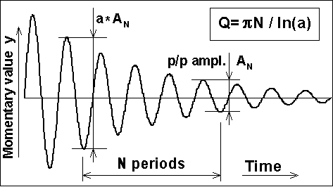
From the impulse response waveform: Pick out two successive periods. The first period has a peak-to-peak amplitude that is some factor a > 1 times the amplitude of the next period. From this you can compute

Q = π / ln(a)              (π=3.1416, ln is natural logarithm)

This works when Q is moderately low, but when high you will not get an accurate value for a, it will be too close to unity. Then, instead measure amplitudes at places N periods apart, compute the formula and then multiply its result by N, Fig 3.

Another, and simpler alternative: find out how many periods N it takes for the amplitude to fall to 1/2. Then
 

qval3.gifFig 3. Finding Q from the impulse response.
Q = N * π / ln(2) = 4.53 * N

We may also refer to the concept of reverberation time as used in room acoustics. In principle this is the time for a transient signal to decay 60 dB, that is a=1000 instead of 2 in the above formula. Also knowing that this time T60  will include N = T60 * F0 periods leads to

T60 = Q*ln(1000)/πF0 = 2.2*Q/F0 = 2.2/B

where B is the resonance bandwidth as coming now.

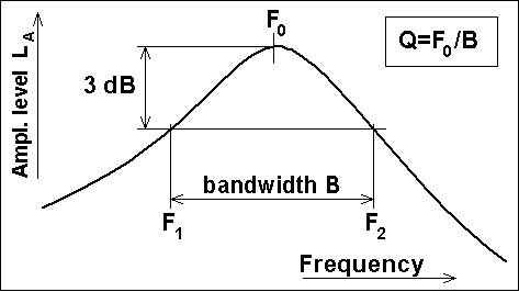
From the frequency response graph: Locate the two frequencies F1 and F2 where the amplitude is 0.707 (-3 dB) of the value at the resonance peak at frequency F0, Fig 4. The difference between those is commonly called the 'resonance bandwidth' B = F2-F1 which obeys the simple relation

Q = F0 / B,  or  B = F0 / Q

This very important relation you can solve (at quite some effort) from the frequency response equation below Fig 1, setting the '3 dB band limit' H=Q/sqrt(2) and neglecting small higher order terms containing 1/Q. So this is accurate only when the Q value is reasonably high, say 5 or more, as mostly encountered in music instrument applications. For lower Q you normally must resort to the basic math that we have bypassed for simplicity, belongs more in the field of filter design, e.g. of loudspeakers.


qval4.gif

Fig 4. Finding Q from the frequency response.

Different resonant structures


qval5.gif

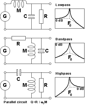
Some features depend on the precise layout of the resonator, e.g. in filters you can divide between lowpass, bandpass and highpass systems. The most common and basic class is that of lowpass systems, Fig 5, top. Such settle to a finite non-zero amplitude when you impose a constant DC excitation. (Bandpass and highpass systems then get zero amplitude). Like connecting a battery to an electric filter, holding still a string pulled sideways, or putting a weight on an elastic bar. This corresponds to the zero dB (reference) amplitude at zero frequency in fig 1.

Now, the important rule for a lowpass: If you impose the same magnitude of excitation (same voltage, force, etc.), but instead oscillating at the resonance frequency F0, then you arrive at the peak. - The resulting amplitude is then Q times bigger than for the DC value of the same excitation


Fig 5. A few sample resonator configurations, in electrical representation. Three resonator elements R, M, and C are driven by a generator G. These are the technically most important ones, there are other possible alternatives.

qval6.gif

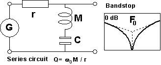
Fig 6. Example series resonator.

So far only parallel resonators have been mentioned. There is another, dual world of series resonators, one example is shown in Fig 6. A most typical difference between them is that when you study some quantity in them the frequency response may be 'turned upside down'. You get a resonance dip instead of a resonance peak.

For the same M, C, and Q the loss resistance element differs widely depending on if parallel (R) or series connected (r). From the formulas in Figs 5 and 6 you can derive


R = r * Q2

In a practical mechanical or acoustical resonator you can often estimate the M and C elements using ruler, balance, or other primitive instruments, but loss resistances are notoriously elusive. Much because often they are not localized to any specific element or place. Indeed, the normal way to estimate them is indirect, you measure the Q value for a resonator where they are part. Then finally you can compute an equivalent loss resistance as

R = Qω0M = Q/ω0C            (parallel circuit), or

rω0M/Q = 1/Qω0C         (series circuit).

Further details must be analyzed in scope of the particular topology of the circuit and quantity studied, something beyond this short note.


2002-06-23, -27, rev 2011-11-02