My belly organ

This little instrument was my first experience in organ building, back in 1983. A test ground for various ideas on how to make one.

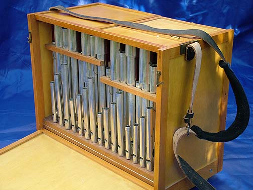
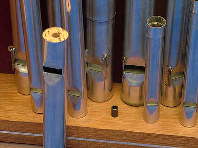
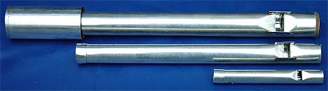
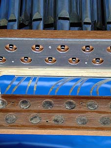
It has 32 pipes, all open flutes made from 0.2 mm tinned iron plate. The pitch range is two and a half chromatic octaves, from f=349Hz to c=2093Hz.

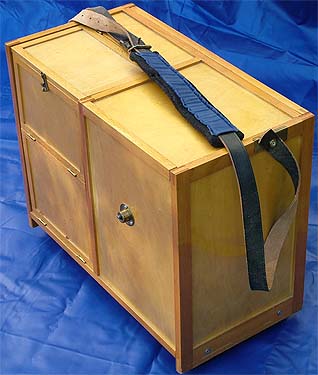
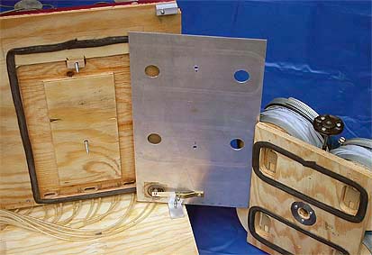
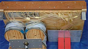
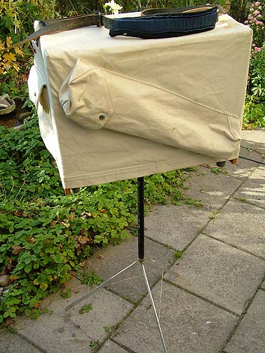
It is housed in a small cabinet made from panels, beech frames filled in with 4 mm birch plywood. The bottom plate is 12 mm plywood, like an attached upright main internal wall behind the pipes. The exterior side panels are screwed to the bottom plate and inner wall at three points each.

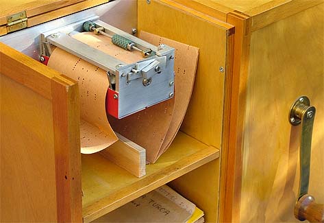
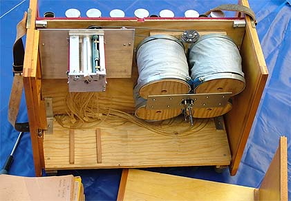
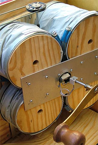
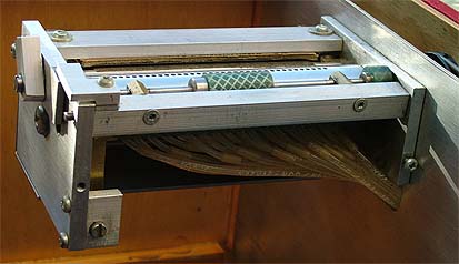
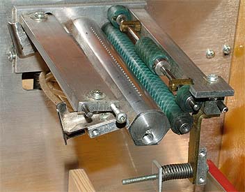
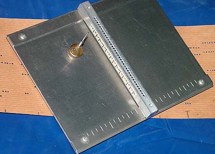
Seen from the operator side, at right there is a connector socket for the crank to drive the air pump. At left, behind covers is at top the tracker mechanism, and below a storage compartment for music books of punched paper strips.
Exterior closed

Open front The pipes stand on a chest with membrane valves, connected with thin plastic tubes to the tracker head. They are placed such that the same note in the different octaves are immediate neighbors. Makes them synchronize if played simultaneously and masks minor mistunings.

The low pipes are longer than the height of the cabinet. They are folded back using coaxial top caps of twice the original pipe area, Haskell style.


mp3 music sample:
Kväsarvalsen
by Artur Högstedt, 1900.
A popular music hall song of its time.

The control paper tapes are fan folded, inspired from the DEC PDP computer tapes of the 1960:s.

The paper width is 100 mm with 1.5 mm holes, slightly smaller than the tracker bar holes.

I typically use 1 cm along the tape for a quarter note, which implies a paper speed about 4 ft/min at tempo 120.
tracker

overall interior
Loosening the side screws about 5 mm the panels can be pulled aside to release the main cover panels. Below the paper tape reading head at left you see the 'nervous system' of tubes from the tracker bar to the pipe valves.

The air pump at right is quartet of small bellows. A fancy design where the four moving lids have a nutating motion. They are all fastened to a rectangular duralumin plate that holds the outer ring of a ball bearing. The inner ring of that bearing is connected to the central crankshaft at an angle.

Here you can see the outer end of the armature holding the ball bearing inner ring. This armature hinges on the axle at the center point of all the bellows. The 1½ turn piano wire spring pushes the armature to an angle and the strength of it defines what the air pressure will be. In the present case about 2 kPa, 8 inches of water column.

The 6 mm crank axle is supported at its inner end by a tubular bearing mounted on the pump plywood base plate. At the end of that bearing is an angle gear toward the top wheel for the capstan drive belt. The organ cover (removed here) holds a bushing to support the crank hub.

The four bellows are made from 125 mm flexible ventilation tube, silicon plastic covered canvas held in shape by an internal steel wire coil. These tubes have limited durability as their creasing is rather uncontrolled. With time they develop minor holes, so once or twice I have replaced them. The ends of the tubes are clamped to round plywood disks where the center holes are covered by leather flap valves.

The highlight of this design is that in case of low air consumption, then the spring is compressed, the angle of the armature decreases, and so does the throw length of the bellows. A very good side effect of this is that you feel the air consumption rate in the crank, it is heavier to turn at loud passages. The spring action also makes these feeders act as a reservoir.
nutating bellows

pump exit
The pump is held against the main interior wall by two screws, loosened here.

At right the four bellows exhaust valve flaps are visible. The air transport channel is shaped by the intermediate plate and a big groove in the main wall. At the bottom of this groove are three oblong holes to let the air into the valve chest.

The intermediate plate holds a spring loaded spill valve. This is probably superfluous in view of the pump operation principle.

The central tracker bar has 32 sensing holes, 1.8 mm diameter at 2.5 mm divisions. Beyond it is a leathered bar to keep tension in the paper tape. On the near side of the tracker bar you see the capstan pinch roller with bearings screwed to the close quadratic aluminum bar. This bar hides the capstan itself, being the same diameter as the pinch roller. The top of the capstan drive wheel is seen at right.

The small handle at extreme left is to lift the tensioning bar and the pinch roller for tape loading. The bottom left screw is to adjust the pinch roller tensioning spring.
tracker

headinterior
In this view the end plate  has been taken away, such that you can see some more of internal constructional detail.

The pinch roller shaft has small rollers toward its ends. These contact the capstan roller outside the width of the paper tape and serve to make the pinch roller actively drive the tape, not just following it.

The tracker bar is made from a 20 mm hexagonal aluminum bar. After its sensing holes were drilled, the sensing surface was turned excentrically in a lathe to render a cylindrical shape.

The wings at extreme left are sideways intake guides for the tape. These should have been made longer in the tape travel direction - as they are they have damaged some tapes at the edge.

The tinned plate pipes are all open. After forming the blanks using various dowels and mandrels they were tin soldered into plain tubes. Then mouth holes were taken up with a saw and a file and the lips were shaped. Little languid plates were cut and soldered in place with lavish amounts of tin from the foot side. The foots were closed with matching cork plugs, with central holes to fit the playing valve exhaust tubes.

Voicing was an ordeal, somewhat eased by adding ears to the low pipes.
pipes

The biggest pipe here has a coaxial cap to make its resonator length larger than available height inside the cabinet.

Fine tuning is done by adjusting the position of the cap, or in the smaller pipes with sleeves at the top open end, secured in place with a solder blob.
pipes

valve
This section sketch shows how a playing valve works.

Pressure is channelled in the hollowed top rail. Below that is a duralumin support plate with 15 mm diameter holes, one below each of the pipe positions. These holes are continued down into the lower rail forming cavities, each connected to its corresponding tracker bar hole with a plastic tube. The several pouches are implemented with one common LDPE plastic sheet. This sheet is pierced with a needle to make 0.5 mm bleed holes at appropriate places.

The output tubes are 6 mm outer diameter, 4 mm inner. The control tubes are MIL grade electrical sleeving 1/8" outer dia, Natvar brand, no aging observed so far.


Here the interior is seen upside down, bottom plate removed. This plate was fastened with two screws to the aluminum brackets at the sides.

The control tubes enter the lower rail of the chest at its side. The dimension of the original tubes was too narrow for reliable function, only short pieces mating the tracker and chest holes are kept.

The lower rail compresses the pouch forming membrane sheet with a dozen screws, threaded into the internal support plate.
from below

valves Removing these screws uncovers the valve interior.

The upper rail holds the small output tubes connecting to the pipes. The duralumin support plate is permanently glued to this rail with epoxi. Together they form the air supply channel.

The lower rail pouch cavities are covered by the transparent polyethylene sheet, for ease of mounting glued in place by strings of rubber cement. The bleed pinholes in this sheet are too small to be visible in the picture.

A drawback with the PE film is its low internal damping. A cure is a small punching of long haired velvet at the bottom of each cavity. This acts somewhat like a return spring to close the valve, but its main function is to damp the membrane mechanically. Depending on load, without it there is some risk an open membrane starts oscillating like an air horn, a very annoying kind if ciphering.

The music is hand punched on paper tapes using this simple tool. Takes a few hours to punch a tune, once you got used how to do.

Timing is monitored from the scale on the lower guide and bar marks drawn on the paper.

It is pretty difficult to cut out the blank tapes from stock. I used razor blades mounted at accurate positions on a bar which i pulled along a sheet, spanned across the room. I got good results using plain parcel wrapping paper. The same in waxed form is more stable, but sometimes tends to slip in the feed mechanism.
punch

on stand
The dimensions of the cabinet are 52 cm wide, 27 deep, and 42 cm high (20.5*10.5*16.5 inches).

The net weight of the organ is 12 kg. The field service accessories sailcloth cover, tripod, and a 30 tune repertoire of punched paper tapes add 2.5 kg. The tripod is disassembled and carried in the oblique pocket of the cover.


Lessons learned:
  • The pneumatic system is very leanly dimensioned, narrow passages and small blowing capacity, such that it takes some care to have everything work.
  • Important to keep paper tension over the tracker bar, to prevent shrieks when a fold passes. This is an inherent problem from reading the paper holes with pressure rather than suction.
  • The pitch of the organ is on the high side - perhaps I should rather have gone for stoppered pipes, bringing it one octave down.

2005-10-19 johan-at-liljencrants-dot-se