Tracker project
A
developing progress report on a venture where the outcome is
rather uncertain. Any comments, suggestions, encouragements, or
discouragements are welcome.
Version 1: 05-06-15, 2: 05-06-25, 3: 05-07-22
Johan Liljencrants
|
For
some
time I have pursued a reactionary project to supplement my
organ MIDI control with a punched paper tape reader. Apart from being
old fashioned there are a number of problematic issues with this, like
making the tapes, feed them reliably over the tracker, and keep
hygroscopic size variation under control. The main positive feature is
that of its visual impact, the solid demonstration of how the organ is
controlled. Also, in my yet limited experience, the presently weakest
link in the system is indeed connected to the electronics system, like
diskette read errors causing abrupt music halts, or inconveniently
complicated multiple control button pressing.
The following covers some key issues of this project, some of
which are almost solved, others still in a planning stage.
Paper tapes
Conventional self playing organs use
either pneumatically read paper
tape rolls, or fanfold cardboard books sensed by mechanical means. The
aim in this project is to combine positive features of each, namely to
use fanfold paper tapes, inspired by the DEC computer tapes of the
1960s. These paper books will then be very compact to store and there
is no call for return spooling. These are to be read pneumatically, but
a main foreseeable problem is how to avoid misreadings at the paper
folds.
The current specification sets out from practical reasons like tape
width 297 mm (long side of A4 paper format) and 200 mm fold divisions.
104 channels on 2.5 mm divisions will occupy 260 mm of punched width.
This number of channels suffices for my organ except its percussive
harp. Possibly the harp can be accommodated using an additional
register
control, not yet implemented. The divisions measure is motivated by my
metric tools for
tracker bar and punch fabrication. This format will not coincide with
any one presently known, but it is anticipated that music arrangements
will
anyway be unique to this organ. Until an automated punch device is
developed I believe computer MIDI printouts will give templates that
are easy enough to use for guiding a manual punch.
Transport machinery
Because of available space this
reader is unusually short in the paper
travel direction, about 280 mm over all. This makes it relatively
difficult to control the paper sideways position, calling for active
devices.
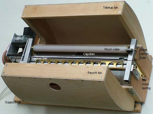
In the drawing below the tape is driven from a payoff bin at left, over
the
tracker bar surrounded by two curved guide plates, into a takeup bin at
right. The tape is driven by a rubber capstan extending
some 2 mm through a hole in the right guide plate. On top is a bridge,
pivoting around its left shaft which also carries a gentle leaf spring
to press the tape against the tracker bar. The bridge right shaft
carries the 'pinch roller' pressing the tape against the capstan. This
is a tube extending the whole width of the tape and is held by ball
bearings at its ends.
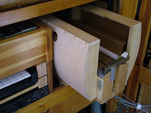
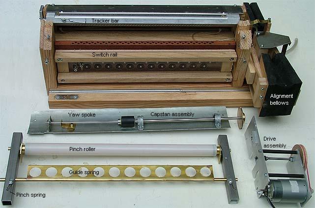
This
photo is a general overview of the assembled unit, mounted with ball
sliders on two support rails. This allows the unit to be pulled out
from its storage position in the organ cabinet for easy access. The
bins and these rails are keyhole mounted such that they are easily
unhooked. The pinch roller axle holds eccentric segments at its ends,
resting against the capstan support plate. This axle can be rotated
somewhat with a small spoke in order to engage or disengage the pinch
roller.
The width of the payoff bin is
just some 1 mm more than the tape
width and is supposed to guide the tape sideways initially. The takeup
bin is some 5 mm wider. It is important that the wide paper tape is
fairly closely guided near
the
tracker bar, otherwise it easily wrinkles as it alternately folds
up and down. On the entry side this is done by the guide leaf
spring, on the exit side by the pinch roller being a long tube rather
than just short rollers.
The outside curvature of the bins appears essential to make the paper
unfold and fold graciously.
The tracker bar is made from 20 mm hexagonal alloyed alumin. Its
sensing holes
are 1.8 mm diameter at 2.5 mm divisions, drilled to the center of the
bar. On the back two oblique sides there are continuation holes to
connect to the
switches. These alternately go to the leading and trailing sides of the
bar, such that the connection holes come at 5 mm divisions. The
coupling to the two switch rails is with short flexible PVC
tubes.
After drilling the holes the bar was excentrically put in the lathe and
the sensing surface was turned into about 15 mm radius.
 |
The
ends of the tracker bar are supported by vertical leaf springs such
that the bar is easily mobile in its axial direction. Two extreme holes
in the tracker bar sense the edges of the paper tape. These holes vent
two balancing bellows that are evacuated via bleeds to the suction
source. This bellows array is geared with an arm to the tracker bar in
order to
align the bar with the actual sideways position of the tape. In the
present
design the bar can move over a range of 3 track divisions in about 2
seconds time. The rocking armature hinges on two central pins and is
held in place by a strong crosswise leaf spring, pivoting on brackets.
This is a toggle pressing the rocker toward its end positions, a
partial compensation for the elasticity of the bellows cloth and the
bar suspension. |
| It is easy
to take out the various subassemblies like the drive motor
gear, the alignment bellows, the curved guide plates, and the bins.
Each is fastened to the wooden main frame with two machine screws. Once
these units are taken away the tracker bar and the switch rails can be
lifted out together. |
 |
The sideways control of the
tracker bar seems to operate well. Still, when the
tracker bar is found to go
toward one side, then the drive mechanism should make the paper tape
wander back toward its correct path. Initially I tried two capstans,
one each side of the
tape, hoping that direction might be controlled using the pinch roller
pressure. In my practical
experience
this does not work. The double capstan was then abandoned in
favor of a single one at the paper
center line.
The key feature is that the feed direction of that
capstan can be controlled to be slightly off axis, in my present
experiment up to +/-3 degrees. When the tracker bar is
sideways adjusted by the sensor holes and bellows, that same excursion
is used to yaw the feed direction of the capstan. After some effort at
the
drawing board I arrived at the following design which indeed appears to
work in the same time as it reasonably simple to make.
 |
The motor
driven capstan shaft (right of capstan in this drawing)
is
rigidly supported by ball bearings at
both its ends (motor end not shown). The shaft capstan end is
approximately ball shaped, resting in a bushing at the center of the
capstan. A hole is drilled through this bushing and the shaft and a
small pin is inserted. With adequate backlash this implements a half
cardan joint. A spoke extends from the other (left) end of the bushing.
The far left end of this rotating 'yaw' spoke rests in a link arm that
connects its direction to the tracker bar sideways position. |
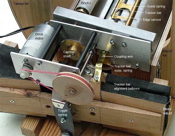
This drawing shows the under side
of the trailing guide plate
which carries the capstan and its control, and also the tracker bar.
The red markings show how the capstan is yawed when the tracker bar is
displaced leftward by the edge sensors and bellows.
Reading switches
These switches are
suction-to-electric converters. They can be
connected in parallel to the present MIDI decoder and serve as an
alternate control option. The design is a
variation on the recipe by Richard Vance at
http://www.mmdigest.com/Tech/vanceSwitch1.html.
Initally I tried a small 8 channel prototype in a plexiglass body, 2.5
mm divisions and 8 mm cavities. Dismissed that as too difficult to make
and adjust. Then made a short 4 channel copy with 5 mm divisions and 15
mm cavities like shown below, which seems to work OK. Major parts for
the complete system are built, but fabrication of contacts withheld
until transport design is finalized.
| To
accommodate the totally 104 switches within managable space requires
multilevel staggering, the first one is to split from the tracker bar
into the two rails. Next level is to alternate between front and back
sides of a rail (black and red in the sketch), and finally
between an upper and a lower row. The general layout is maybe seen
in this sketch of the end of one of the rails. |
|
The central part is a 12*80*330 mm
mahogany piece with 2*2*13
pouch cavities, 15 mm diameter. On each side, over these cavities
is a 1.5 mm plexiglass plate with a glued-on wooden frame to carry the
contact wires. These plates are drilled in the same operation as that
for the underlying cavities. The pouches are formed by a coherent sheet
of pouch leather (red below), compressed without glue between the 1.5
mm sheet
and the wooden base. Outside this are 3 mm plexiglass plates carrying
contact adjustment screws in threaded holes, and finally wooden bars to
hold the complete assembly together. The inner sides of these bars are
made slightly convex in order to distribute their compression force
more evenly along the rail - there is little room for compression
screws except at the ends of the rails.
|
This drawing shows more detail
on one single switch, for clarity
neglecting its neighbors.
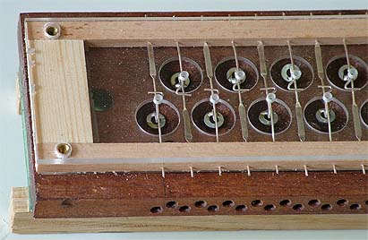
The photo is from before adjustment screws and pouch leather are
installed.
|
 |
The internal volume where the contact
springs are located is connected
to the suction source. For each cavity there is a 0.8 mm bleed hole
drilled through the 1.5 mm plexiglass, leading to the channel toward
the tracker bar. It is a fairly exacting operation to perforate and
mount the pouch leather sheet to match with these bleed holes.
The contacts are made from 0.8 mm sterling silver wire. Each contact is
two parts, one 'fixed' albeit adjustable with a screw, and one moving
with its end actuated by the pouch. The stem of the moving contact is
flattened into a leaf spring, 0.25 mm thickness. This flattening is
done using a steel bar with thickness control shims added. The contact
wire is placed between that bar and an anvil and the bar is hit with a
sledge hammer. Hammering is repeated until a micrometer or caliper
tells the correct thickness has been reached. The end of the moving
contact is bent and tin soldered to a small washer that rests on the
middle of its pouch.
After preliminary shape adjustment the contact wires are locked in
place in their mounting holes with cyanoacrylate glue.
When the tracker hole is covered, then the whole unit is under the same
suction, the contact spring presses the pouch into its cavity and the
contact is open. With an open tracker hole only the contact cavity is
under suction and the pouch lifts the contact spring until it makes to
its fixed counterpart.