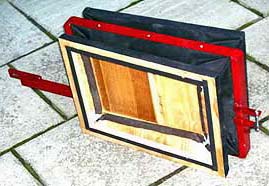
The moving boards of the feeders are mounted on welded steel frames
(red)
that have rubber hinges at the extreme left side of the cabinet frame.
That way the feeder bellows move more like a parallel motion than in a
plain wedge bellows, an expedient to maximize bellows air displacement
while keeping size down. - After disconnecting the screw joints
on
the
feeder frame shafts I can easily lift the entire bellows and crankshaft
assembly out of the cabinet for maintenance.
The following image sequence shows details of the primary air
regulation machinery, as parts are successively removed.
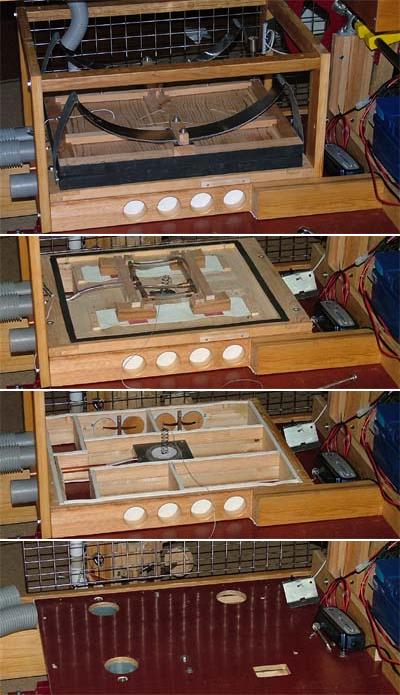 |
The reservoir
bellows is compressed by two leaf springs, hinged on yokes at their
ends, defining the raw 3 kPa pressure. There are three different
sensors of reservoir lid position: 1. Far right a potentiometer controlling bellows motor speed at normal use. 2. Middle, a string pulling an input regulator valve when an external feeder fan is used. 3. Left, a string to a pallet valve, pneumatically controlling the reservoir input valves when the unit is hand cranked. |
| The four
reservoir input valves have little piggyback bellows. When hand
cranking at too high speed (alt 3 above) these hold the valves open,
such that air flows back into the feeder bellows. |
|
| On top of the
floor is a frame divided into several compartments. Here are eight
round intake flap valves. At center is the regulator valve to control
the inflow of air when an external fan is used for supply. |
|
| Below this 'floor' are the
feeder bellows. These alternately suck and blow air through the three
round holes and one rectangular. |
An external fan is an additional air supply alternative. There is an inlet and back check valve for that in the valve frame and that air will then enter the central compartment of the frame. From there is a passage up to the reservoir, central dashed hole in the drawing. This hole is covered by a bellows unloaded disk, connected with a string and spring to the reservoir lid, works as a pressure regulator.
The springs to press down the reservoir lid used to be a bit
problematic.
Earlier i have used a set of harmonium compass springs for the purpose,
but they were tricky to balance in order to have the lid moving in
parallel. Next I followed a conventional design using helical springs
with
extended arms, tied down with straps. Heated and shaped an old
athlete's
arm strengthener made from 6 mm steel wire. Now finally, a pair of leaf
springs, resting at the center of the reservoir top board and with
yokes
at their ends. These work very well to keep the board moving in
parallel.
Each
spring is a stack of four 1*50 mm spring steel bands of progressive
length
up to 500 mm, same as the length of the reservoir.
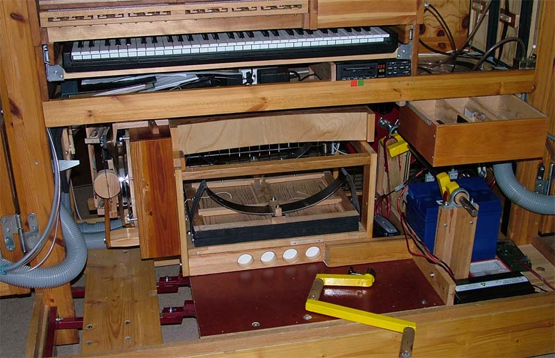
Here is a total view of the bellows assembly, with the drum machine
riding on its frame. The hand crank is resting on the floor. Left of
the middle floor you see the joints of the feeder bellows arms. The
blue thing at right, below the open accessories drawer, is the battery.
On the shelf, between that drawer and the keyboard, is the RD-70 MIDI
player. A red and a green patch locate its stop and start buttons. At
the right end of the shelf is a small brass box. This is the
water
container for a pressure manometer tube running up the adjacent pillar.