The essential feature of the memory
function is that you set up what
ranks to use with short impulse commands, and these settings are then
kept
until another command is given. Meanwhile you can change settings
manually.
See the cross section drawing beside. The rails a, b, and c are divided into two sections holding 8 output amplifier valves each, while the other rails extend over all 16 positions. The 3 kPa air supply is present in channels along the whole unit, marked P, in the c and g rails.
The memory unit is rails d and f, each with a row of 16 pouches. Pouches in an upper/lower pair act on a corresponding lever e that is hinged using a 0.1 mm brass sheet spring. The lever carries a small neodymium magnet that attracts to the closer one of the iron adjustment screws in d and f, above and below (blue). This attraction makes the memory function, such that levers stay in the position set.
At rest all pouches in d and f
are pressurized, so
they
give little net force on levers e. When a magnet in g
is
energized, then its corresponding pouch in f is vented, and the
d
pouch will press the lever down. This 'on' position opens a valve hole
in rail d. This in turn operates the amplifier valve in a-b-c-d
which will vent its reg output, tubed to its
row
of register pouches in a chest.
One of the 16 positions in the unit is
denoted as 'cancel', 'clear',
or 'reset'. It is like the others, except its d pouch is
replaced
by a spring. It is the output of this amplifier valve that feeds the clr
input.
When you vent the single clr
input, then
all
pouches in d are evacuated, allowing the pouches in f to
push levers up to the 'off' position. But, if at the same time a set
command
is given to one or more magnets, then their f pouches are also
vented
and nothing will happen to those levers. They will then stay their
earlier
position,
on or off.
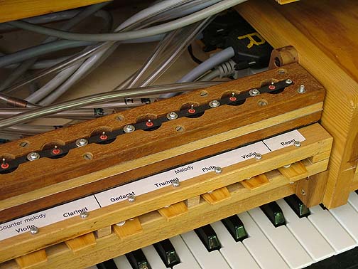 This photo shows the controls shelf slightly pulled out
on its guides, and below it the MIDI keyboard that is one of the
alternate means of control. Extreme right is the box holding the MIDI
decoder and patchboard. This is where all the cables for the various
chest (note) magnets originate.
This photo shows the controls shelf slightly pulled out
on its guides, and below it the MIDI keyboard that is one of the
alternate means of control. Extreme right is the box holding the MIDI
decoder and patchboard. This is where all the cables for the various
chest (note) magnets originate.
Behind the register unit is a worm's
nest. Beside the cables there are PVC tubes going from the register
unit to the pouch valve rows that enable the various pipe ranks.