Wind chests
The four wind chests have in all 8+12+30+25=75 note valves (plus two
spares in the melody chest, one in the counter melody). A note valve
feeds a note channel, and in this channel a secondary set of
'register valves' controls which pipe ranks on the chest are actually
blown. In the bass chest every note valve serves 2 pipes, in the
accompaniment and counter melody chests 3, and in the melody chest 4.
Each note
valve
consists of a small 150 Ohm Reisner chest magnet (OSI #5501.32), in
turn
controlling a bigger pouch valve for air into one note
channel. These pouches are from 75 mm diameter in the bass chest, down
to 40 mm in the melody chest. This is about the same dimension as the
inter note division along the chest, so the note valves as well as one
of the pipe ranks had to be
staggered
a little in order to give enough room for the pouches.
Here is a section through the melody chest showing details for
one note. The chest is
basically
a stack of 4 perforated boards (identifiable from the hatching
directions)
held together by 36 joining bolts and is easily (?) disassembled
removing
these. The top and bottom boards each are split into two 16 note
sections
while the air duct and the register pouch boards extend the total 1550
mm length of the chest.
In the top board, below each pipe rank, is the set of register pouch
valves,
controlled
in parallel. These work as pneumatic correspondents to sliders. In this
drawing the second rank from left is enabled, its control channel is
vented.
The other three ranks are shown as cut off with their control channels
under high (3 kPa) pressure. The outlet tubes protrude upwards and have
slightly conical ends to match corresponding foot holes in the pipes.
|
|
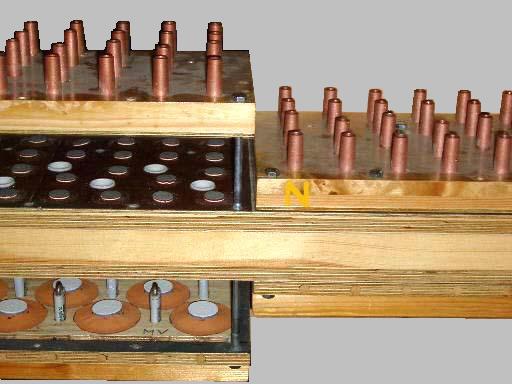
The following
photos show at right the top and bottom panels in
place,
at left in 'exploded' view. First seen from slightly above. At bottom
the
note valve pouches interlaced with the chest magnet windings. Middle a
silicon tightened cloth forming the register pouches with little
pallets,
matching the top output copper tubes that accept the pipes. Between the
small pallets are the white ends of the output tubes of the note
valves. |
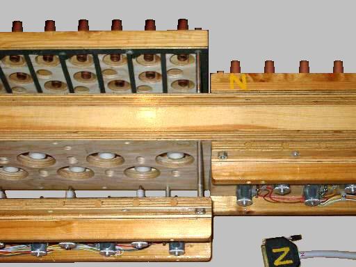
| And
from slightly below: Here you see the lower
valve tube ends that
seat the pallets. At bottom parts of the chest magnets are visible,
also
part of their wiring. |
|
These pictures reveal redundant features remaining from earlier
attempts.
One thing is that all pouches have a matching hole in the panels
opposing
the gluing surface. My original version did not have individual pouches
- the whole pouch area was instead covered by big polyethylene sheets.
Much simpler, but a bit sloppy to get under control. Also there were no
chest magnets, the playing valve pouches were pneumatically remote
operated.
In the lower panels you can see the plugged holes after the bleed
adjust
screws, control tube nipples went in the opposite side. Abandoned that
for reasons of repetition speed, in favor of electrical distribution.