In a flue pipe, what happens to the tone in case you nick the flue and/or add a bridge over its mouth? The classical answer is that nicking speeds up the start and that a bridge will prevent overblowing, allowing for lower cut up and stronger harmonics. Here are some experimental results to illustrate these effects, separately and in combination, applied to one and the same pipe.
The experimental wooden flue pipe is for MIDI note #63, f=175 Hz. Resonator length is 891 mm, 55 mm square. It was blown with 2 kPa (8 inWC) repetitively in a cycle of about 270 ms on and 160 ms off, controlled from an oscillator and an electropneumatic valve. This automatic fast repetition was very convenient in voicing the pipe. I also have the impression this warns you from going into such extreme settings that could jeopardize stability. In the faily short 'silent' interval the pipe oscillations mostly fade away, but not completely. This means that each onset has some minute influence from the preceding note. At times I could avoid unstable situations where successive notes sounded markedly different from each other, for instance with a too low cut up.
The recordings were done from an electret microphone 0.5 m in front
of the mouth in a fairly damped living room. They also contain a fair
amount
of background fan noise that is hopefully not too prominent.

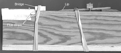
The pipe was made with an adjustable flue made from two 2*7*70 mm duralumin inlay strips and an adjustable upper lip. In this side view you can see the ends of the flue strips, resting in grooves in the languid and the cap. The inner strip slopes at about 10 degrees and the airband thickness is controlled with small shims between the strips. The gap between foot cavity and cap, due to these shims, is covered with tape. In the figure is also a bridge, held in place with a rubber band. The precise depth position of the upper lip is adjusted with a wedge between the pipe body and the upper end of the lip board (extreme right in the picture).
Two sets of strips were prepared for a nicking experiment. In one,
clamped
together, a row of 2 mm holes were drilled along their common surface
at
4 mm centers. The strip in the cap was turned with either its flat or
its
grooved side inwards. This represents a very considerable nicking.

In the other set with a more moderate nicking, on recommendation from Richard Vance, nicks about 0.5 mm deep and 1 mm wide were made with a hacksaw, inclined at an angle of 30 degrees from the airflow direction, same 4 mm division step. Using these (case #d below) both the inner and outer strips had the nicks toward the flue and would cooperate to produce rotational components into the jet.
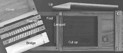
Here is another view, with the parts disassembled. The semicircular and oblique nicking grooves are visible in the respective metal strips. The bridge is slightly curved on its inside. A thin leather gasket is glued at top of the cut up hole, to seal against the upper lip board.
Seven different cases were recorded, as outlined in the following
table.
| Case # | Cut up H (mm) |
Flue thickness T (mm) |
Flue area (mm2) |
Comment |
| 7 | 28 | 0.4 | 20 | 'Low' voicing, no nicks |
| 8 | 28 | 0.4 | 40 | Nicks, adding to flue area |
| 9 | 28 | 0.8 | 40 | No nicks, increased flue area |
| a | 19 | 0.8 | 40 | No nicks, bridge |
| b | 22 | 0.4 | 40 | Nicks plus bridge |
| d | 20 | 0.8 | 40 | Oblique nicks plus bridge |
| e | 28 | 0.8 | 40 | Edgetone, pipe muted, no nicks |
T was measured with feeler gauges between the flue strips. In each
of
the cases the depth position of the upper lip was adjusted for tone
stability
and promptness of speech. This position was reasonably easy to find
using
the automatic intermittent blowing, but is arbitrary in the sense that
the voicer's opinion is a factor. Position varied a few 1/10ths
of
a millimeter between cases, too small differences to be reliably
recorded.

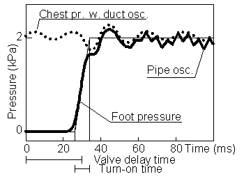
This is a stylized graph of what the pipe foot pressure looked like, as recorded from a small pressure transducer. Time 0 is when the electrical signal triggers a Reisner chest valve controlling a big pouch note valve. The pouch flips open in about 8 ms, but before this happens the pouch has to be evacuated which takes effectively some 30 ms. The supposedly constant chest pressure has a variation imposed on it from the load. When the pipe airflow starts there is a momentary pressure drop in the chest which causes a damped oscillation with the chest and its supply duct as resonator elements. Similarly, when pipe flow is cut off another transient starts - the variations in the early part of the graph are remnants from the previous cycle. When the pipe eventually starts speaking (from about 60 ms) you see traces of the pipe tone superposed. The drop in the valve makes foot pressure slightly lower than chest pressure.
Case #7 is termed 'Low voicing' as the cut up H is relatively large with reference to the airband thickness. In all the other cases the airband is thicker - the total flue area, including nicks when present, was held constant. Instead the cut up was adjusted to what I judged as a minimum, compatible with a good tonal result - 'High voicing'.
It should be stressed that the particular results shown here partially depend on my own taste and prejudice in how to voice. Also there is a considerable chance element, but hopefully minimized by the use of a single pipe and the measurements being done closely in time in a fixed setup. It seems the classical notions of what should happen do hold. And even though the differences between these voicing alternatives are substantial the audible differences in tone are not always rightaway obvious.
Johan Liljencrants
2001-06-05,
rev 2003-12-28, 2009-02-25
http://www.fonema.se/