End Correction at a Flue Pipe Mouth
by Johan
Liljencrants
A simple notion is
that the fundamental resonance of a pipe
occurs when the sound wavelength is half or a quarter of
the resonator
length. It is however well recognized that the practical
frequency
comes out lower than this, you have to apply an end
correction, the
pipe appears to be acoustically somewhat longer than its
physical
length. A formula for the basic mechanism behind this is
theoretically
derived, then expanded into the case where the open end
area is made
smaller than the pipe cross section. The end correction was experimentally determined for several pipes with mouths extending 360 and 90 degrees of the circumference. Formulas are given to compute the end correction, using optimal coefficients found from these measurements. |
The
pitch f of
flue
instruments like the flute, organ
pipe, or whistle is predominantly controlled by a
resonator length L.
This length is closely connected to the wavelength |
|
Let us initially inspect a quarter
wavelength
resonator tube of length L
and area A,
closed at one
end. This tube has a total
acoustical
mass |
A theoretical basis
for
computation of the end correction is the 'radiation
acoustic impedance
of a circular
piston', reproduced here. This impedance tells the
ratio of
acoustic pressure at the piston, divided by the flow rate
induced by
it. The piston does not physically exist, it is an
abstract
theoretical vehicle to state that one assumes the air
speed to be the
same at all places across the tube end. This is a good
approximation, but not exactly true in reality, since air
viscosity
reduces the flow rate in the boundary layer very close to
the tube
surface. Two different cases are illustrated here. In blue for a free tube end and in red for a baffled tube, i.e. when a wall limits the external sound to spread only into a half space rather than all around. There is a critical frequency, typically taken as kr=1, which implies that wavelength equals the circumference of the piston/tube. At higher frequencies, or greater r, the tube end tends to impedance match the ambience such that the tube does not act as a resonator, but just a transmission line. The scale of whistles and organ pipes is always such that kr is substantially less than unity, so what applies to our problem is the left half of the diagram. The impedance Z is composed from two parts, the real resistance R and the imaginary reactance X. |
|
R tells
the
in-phase
component of the pressure to flow ratio. A given flow U will
develop a power W=RU2
that is lost from the resonator and is radiated into the
ambient space
to
become a useful sound. Normally this 'radiation
resistance' is a
major determinant of the resonator Q value.
Since it is rather immaterial whether the tube is
circular,
quadratic, or even moderately oblong rectangular, let us
here stick to
the correction expressed in terms of the tube area, such
that it
amounts to
|
Now let us narrow the open end of the tube
with an aperture, into a mouth area B,
less than or equal to
the tube area A.
This means
that we effectively remove the classical end correction
and instead add
the acoustic mass
of a tube of area B.
The physical length of this tube is essentially
zero, but we have to add a new end correction for this
one, indeed for
both sides of its
aperture. On the outside we can simply assume the same
formula as
before. Similarly might apply also
to the inside
of the aperture, but
only when B is appreciably smaller than the tube A. With a
growing aperture area such an internal end correction
decreases to
ultimately vanish when B
reaches A.
There are
plausible models for
this, but for the present we
neglect any
internal correction.
The paradox is resolved by the fact, that
when the
area B is made
smaller, then
the additive
We would have appreciated when the
coefficient in
this result had rather been 0.34 , such that it complied
with the
original formula when B=A.
But when we assume the mouth aperture to be partially
baffled, that
would
correspond to a credible increase in the coefficient. The importance of this theoretical
derivation is to
suggest that the end correction
is basically proportional to tube
area over square root of mouth
area. It remains to find practical values for the
proportionality
factor, and how to specify resonator physical length. |
![]() The system was excited by an external loudspeaker, driven from a tone generator, and frequency was monitored with a counter to 0.1 Hz accuracy. A midget microphone was placed inside the resonator such that the resonance peak could be located by adjusting frequency. Having found the -3 dB points fa and fb of the resonance peak, then the resonance is found as f1=(fa+fb)/2 while the quality factor Q=f1/(fb-fa). Knowing f1 and sound speed (ambient temperature should be accounted for) the actual quarter wavelength is computed. This then equals the physical resonator length L plus a sought, experimentally determined end correction. This is compared to the theoretical model, the right member of the expression The various experimental values were collected in an Excel spreadsheet. A final step is to find values for the coefficients |
A
set of cylindrical tubes were used, where length L from stopper to end
was in all
cases set to 187 mm, corresponding to resonance in the 400
Hz range.
The internal diameters were 13.4, 24.5, 46.0, and 69.5 mm,
wall
thickness between 1.5 and 2 mm. For each, a block of same
outer
diameter was placed at variable
distances H from
the open end
in order to simulate the pipe languid and foot. |
|
![]() The two coefficients The small colored figures tell values of H. Here resonator length is taken as the tube proper, such that the case of infinite cutup can be included. But common practise is otherwise to define the resonator length as the sum of L and H. |
![]() |
It is interesting to note the additional term with the cutup H. This apparently accounts for an extra distance for the sound wave to travel, from the end of the tube to an effective center of the mouth opening. This may come from that the mouth is located at the side of the tube rather than centrally at its end, as was postulated in the theoretical model. |
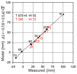
The following data were obtained from two regular square stoppered wooden organ pipes where the cutup could be varied by moving the labium. This means that the front plate length L differed between data points, while T was constant. | |
![]() Here the common way, defining the resonator length as T = L+H is shown in the lower formula and the graph, while the upper formula uses the front plate length L. The two formula alternatives render identical results for the effective length Le, which is the quarter wavelength at fundamental resonance. These two pipes render the same optimal coefficients once the length T of the bigger one was artificially increased by 8 mm. This extra correction is the thickness of its pipe walls, apparently introducing an extra length or a baffling effect. Here the RMS error between data and model is 1.7 mm. |
Because this graph and formula is based on the total length T, the end correction becomes negative at sufficiently large H. |
The
most
obvious difference against the previous 360 degree mouth
is that
the coefficient for the |
Conclusions The foundation for the mouth end correction was theoretically established as having a factor It must be noted that the fundamental speaking frequency of the pipe when blown is not precisely the same as the resonance frequency studied here. When blown, the pipe adjusts to whatever phase angle is imposed by the flue exciting mechanism, most probably characterized by its Ising intonation number. This, in turn, is determined from cut up, flue airband thickness, and blowing pressure. References Beranek L L (1954): Acoustics. McGraw-Hill. Ingerslev F, Frobenius W (1947): Trans. of the Danish Acad. of Technical Science, No 1. Ising H (1969): Über die Klangerzeugung in Orgelpfeifen. Diss.,Technisches Universität Berlin. 2006-09-30 JLs |