Leakage rate meter for bellows materials

Johan Liljencrants

This note presents a simple equipment to measure the air leakage rate in materials used for bellows and pouches in organs and other musical instruments. The measurement principle is that you expose a specimen to an air pressure difference and measure the time it takes to displace a known volume through it. The result can be formulated as a linear air speed going through the material at a specified pressure, or as a characteristic discharge time independent of pressure.

The figure shows a rig for the purpose, built from two PET bottles and various accessories on a vertical stand. The centers of the threaded bottle covers are punched out to accept 16 mm plastic tubes. The joints are soldered together using a hot melting plastic glue gun and a hot air gun, such that they become air and water tight. The tubes from the two bottles are joined with a flexible hose.

The upper left bottle is at a fixed position at top of the stand. The lower right bottle has its bottom cut off and can be slided up and down along a guiding rail. A suitable amount of water is filled into this container. The range of under pressure in the left container can now be controlled and is measured in terms of water column H using the scale. A 6mm ID plastic tube joins the topmost 'suction cavity' to the specimen. On its way down this tube penetrates the big tube below the left container, also this passage is soldered tight with melting glue.

For measurement do the following procedure. With the specimen disconnected, raise the right container to a top position to make the water levels equal in the two containers, somewhat above the zero mark on the scale. The specimen is then connected to the thin tube and the right container is let down to an experimentally pre-determined position. The water level in the left container will then gradually sink due to the specimen leakage. Using a stopwatch the time is found from when the left container level passes the scale zero mark until it has gone down another e.g. 50 or 100 mm.
For the time measurement to be valid it must be considerably longer (say maybe 5 times) than what you would obtain doing the same maneuver with no specimen connected, with the thin tube open. If the time is shorter the specimen leaks too much to be accurately measured, the flow resistance in the meter tubes adds an undesired error. In such case you may try using a specimen of smaller area.

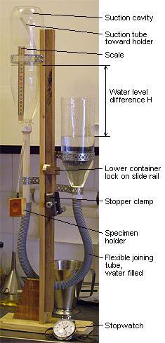
The pressure difference across the specimen is most easily denoted in terms of the water column H. It may be regarded as a slight drawback that H varies throughout a measurement interval. Using the scale you should determine the initial and final values of the water column height H.

Interpretation of measurements

A known area As of the material under test is exposed to an air pressure difference P. It then takes the time T to draw a volume V of air through the specimen.

Pressure P. A representative value for the pressure is the average of the water columns H at start and end of the time measurement interval. These are determined with a graduated ruler.

Volume V. The diameter Dc of the upper left container makes its cross sectional area to be Ac= Dc*Dc*(pi)/4, (pi)=3.1416. When the upper left water level sinks the distance L during the time measurement, then the air volume displaced is V=Ac*L. Together with the recorded time T this renders a leakage flow rate to be V/T, for instance in cm3/s or in3/s.

The area of the sample specimen is similarly found from the test cavity diameter Ds to be As= Ds*Ds*(pi)/4. This leads to a first normalized measure of leakage rate, namely the volume flow per area of the specimen vl=V/(T*As). The dimension of this comes out simply as linear speed, for instance as cm3/(s*cm2)=cm/s, or in3/(s*in2)=in/s. At the actual pressure difference, this is the linear speed of the air stream passing through the material.

An important find in my experiments is that this leakage air speed vl in leathers and similar supposedly 'airtight' materials is very closely proportional to the pressure. This suggests another even more normalized measure, namely in terms of a characteristic discharge time. Take the pressure in terms of average column height H and divide by vl. Then you arrive at a time Tc in seconds, described by the formula
                H*As
Tc =  T* -------
                L*Ac
where
H is the average pressure in terms of water column height,
L is the distance travelled by the upper container water surface,
T is the time do that travel,
As is the area of the sample specimen, and
Ac is the cross sectional area of the upper container.
H and L must be measured in the same units, no matter whether in e.g. inches or centimeters, and corresponding requisite applies for the areas As and Ac, e.g. in2 or cm2.

To visualize the meaning of this characteristic time, think of the volume given by the specimen area As multiplied by the pressure defining column height H. Tc is the time it takes for this volume of air to leak through the sample at that pressure.

It must be noted that flow is not proportional to pressure when the sample is a small aperture, like e.g. a bleed cup.

Experimental data

Measurements were done on the following few samples that happend to be at hand in the workshop:

Designation
Thickness
Description
Paper 80 g
0.10 mm
Plain office copying paper
Tyvek
0.10 mm
Polyolefin fiber material, used for untearable envelopes
OSI tan
0.25 mm
Thin tan pouch leather, from Organ Supply Industries
Arndt wh
0.30-0.60
Thin white sheepskin, from Arndt Organ Supply
Å&L tan
0.30-0.40
Thin tan bellows leather, from Åkerman & Lund, possibly orig. from Laukhuff.
Apparently surface treated for reduced leakage, bad glue adherence to grain side
OSI mot cloth
0.35 mm
Thin motor cloth, rubber between two cotton sheets, from OSI

Specimen holders were wooden blocks 50x50x19 mm with 25 mm dia. cavities drilled 7 mm deep using a Forstner bit. The cavities connected to the outside with 4/6 mm tubes and were internally sealed with hot hide glue. Initially samples were clamped between a pair of such blocks with a 1 mm rubber gasket toward the suction side. It appeared that repeated measurements on the same materials gave rather variable results, probably because of uncontrolled extra leakage in the gasketing. To increase the measurement reliability, for the results shown below the samples were instead glued to individual test blocks using hot hide glue.
The three leather samples are relatively elastic and pliant and form a spherical dome shape about 3 mm deep at 250 mm WC. Some of this shape remains when the suction is relieved. These materials are suitable for making pouches. The paper and motor cloth samples are very stiff by comparison and the dome depression is only in the range 0.4 to 0.7 mm. That stiffness makes them useless for pouches, but they are still good for bellows where the material is bent rather than stretched.
This figure shows the characteristic time constants Tc found for the specimens, for most of them for three different cases. The blue bars relate to the case of the left water surface descending 50 mm, H falling from 300 to 200 mm, hence average pressure 250 mm WC. The red bars are for the surface going down another 50 mm, H from 200 to 100 mm, average 150 mm WC. The rightmost sample for motor cloth is an exception. This material proved to be exceptionally airtight, Tc around 1000 seconds. This sample was measured using H from 300 down only to 280 mm.

The fact that the blue and red bars have almost the same height is the experimental justification for using Tc as a characteristic, it is essentially independent of the pressure used.
The paper and leather materials fall in a Tc range from about 10 to 60 seconds, corresponding to a leakage air speed vl from around 2 down to 0.4 cm/s at the pressure 250 mm WC.

The air tightness can be improved by impregnation. A classical way is to treat the leather surface with a rubber solution. In this experiment I used silicon RTV (Room Temperature Vulcanizing), a material that in my experience is vastly better than any natural rubber what concerns long term stability. This transparent paste was diluted with about 5 volume parts of medical grade benzine into a consistency like thin paint. It was applied with a brush and it quickly soaked into the material where it was left to vulcanize to the next day. Measurements show that air thightness improved typically about tenfold, black bars in the diagram.

Leakage in complete bellows

The measurements so far reported illustrate the materials in an initial undisturbed shape. The following was to see how  well these data hold in an applied situation. The case examined is a few samples of 29x90 mm secondary windchest bellows, part of an ongoing effort to restore the Skandia Theatre organ in Stockholm, Wurlitzer style E opus 1254, installed in 1926.
These measurements on complete bellows (before and after silicon treatment) essentially confirm the ones above for flat samples, but also raise a few comments.

The bellows were connected to the meter device using a soft rubber plug rather than by semipermanent gluing. It was fairly difficult to do this reliably despite the connection holes in the bellows leaves were internally sized with glue, and the plugs were inserted accurately and vigorously. Still some variations in the measurements may be due to small leaks in the connection.
The two groups of three using the same leather show a spread between individual bellows. This apparently depends on thickness variation in the leather.

The silicon impregnation was less effective with the Å&L tan leather, at one instance even counter productive. This leather appears to be pre-treated in some way to reduce leakage. Also hot hide glue does not adhere well to its grain surface unless this is first rubbed with sandpaper.


2007-10-03